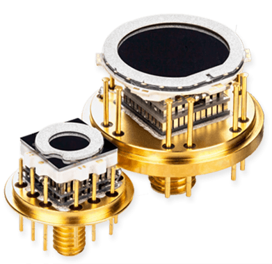
Device Parameters
Photon Detection Efficiency
The photon detection efficiency (PDE) is defined as the number of photon-discharged microcells divided by the number of incident photons.
For SiPMs the PDE value depends on the applied overvoltage (cf. Figure 1) and the wavelength of the incoming photon (cf. Figure 2). First one is due to the fact that the Geiger efficiency is increasing with increasing overvoltage until it reaches its maximum. Second one is due to the very different interaction- and absorption behavior of light with different wavelengths in silicon. The KETEK SiPM has been optimized for blue light. This is amongst many other applications a perfect match for many scintillator materials like LSO, LYSO, NaI:Tl, CsI, GSO, Anthracen, etc.
- QE = Quantum Efficiency
= Geiger Efficiency
- GE = Geometrical Efficiency
- λ = Wavelength
- V = Bias Voltage
Figure 2: PDE vs. wavelength of the incoming photon with a peak sensitivity at 420 nm. All stated PDE values do not include noise effects like dark counts, crosstalk or afterpulsing and are based on Poisson statistics based measurements.
Example shows WB Series SiPMs at 5 V overvoltage.
Linearity
The photon detection efficiency (PDE) is defined as the number of photon-discharged microcells divided by the number of incident photons.
SiPMs show only in a limited range a linear response to the incident light. The two main parameters causing saturation are the limited number of available microcells and the recovery time of the microcells. The number of microcells is the only limit in case of very short light pulses (shorter than the recovery time) like the one shown in the example with 70 ps length. For longer light pulses like in the example for 1 µs length, it is also important that the cells recover as fast as possible again. Therefore in terms of linearity, PM3315-WB shows a linear behavior over a wider range compared to PM3325-WB, as it has both a higher number of cells (38800 vs. 13920) and also a shorter cell recovery time (13 ns vs. 40 ns). PM3325-WB instead has a higher microcell fill factor and therefore higher PDE than PM3315-WB.
Figure 1: Linearity of PM3325-WB measured at 4 V overvoltage and 420 nm.
Gain
The Geiger discharge of a micro pixel is proportional to the applied overvoltage ΔV = VBias – VBreakdown and the microcell capacitance. When hit by a photon, each microcell produces a standardized signal regardless of its position on the SiPM. Due to almost no avalanche fluctuations the excess noise factor is very low and close to 1. Therefore the gain of a SiPM is scaling linearly with the applied overvoltage. Typically the gain of KETEK SiPMs is in the range of 105 to almost 107 (cf. Figure 3). Due to such a high gain typically single photons are already resulting in amplitudes of several mV at 50 Ω load.
- CPixel = Capacitance of Microcell
- ΔV = Overvoltage
- GE = Geometrical Efficiency
- e = Elementary Charge
Temperature Coefficient
Avalanche diodes have a positive temperature coefficient of the breakdown voltage. This temperature coefficient is directly affecting the applied overvoltage and also the gain. The temperature coefficient of the gain is decreasing with increasing overvoltage. KETEK SiPMs show a very low temperature dependency which can make an adjustment of the bias voltage with temperature unnecessary and therefore can reduce system complexity and cost.
- G = Gain
- ΔV = Overvoltage
- VBD = Breakdown Voltage
- T = Temperature
Noise Effects
Dark Count Rate
Pulses not being excited by incoming light are termed as dark pulses. They are triggered by thermally generated electrons and the frequency is termed as dark count rate. It is dependent on the overvoltage since higher overvoltage increases the breakdown probability (cf. Figure 5).
Secondly the dark count rate depends on the carrier density in silicon. Therefore it shows a strong dependency on the temperature. Roughly every 9°C the dark count rate is reduced by a factor of 2 (cf. Figure 6).
Figure 6: Dark count rate versus Temperature for the WB Series.
Optical Crosstalk
Depending on the number of electrons created during the Geiger discharge of a microcell about 3 to 50 secondary photons (in average three photons per 105 avalanche electrons) with a wavelength range from 450 nm to 1600 nm are emitted isotropically from the fired cell. These secondary photons are just like the incoming light able to cause a further Geiger discharge in case they are able to reach any other charged microcell within the SiPM (cf. Figure 7).

Figure 7: Schematic of optical cross talk mechanism.
(1) Most obviously the secondary photons can travel directly to a neighboring cell (direct optical crosstalk),
(2) A secondary photon is able to generate an electron-hole-pair close to a neighboring cell. The carriers can diffuse to the microcell and cause their discharge (delayed optical crosstalk),
(3a, b) Secondary photons, being reflected at one of the various interfaces like e.g. package boundary or SiPM backside, can reach a neighboring cell via an indirect path (indirect optical cross talk).
The optical crosstalk mechanism according to (1) can be suppressed by a deep optical trench isolation between the individual microcells. In case the trench is deep enough, it helps also to suppress the crosstalk according to mechanism (2) by covering a larger solid angle.
Figure 8: Optical crosstalk probability versus overvoltage for WB Series SiPMs. It includes direct crosstalk which dominates and also delayed crosstalk ( < 0.1%) which is almost negligible.
Afterpulsing
During the breakdown and avalanche creation in a microcell, charge carries can get trapped and their release can happen during a period of up to several µs. KETEK SiPMs show a very low afterpulsing of less than 1% (cf. Figure 10).
Figure 10: Afterpulsing probability of the WB Series SiPMs which show a very low value of < 1%.
Example shows the WB Series SiPMs.
Breakdown Voltage
In contrast to APDs, SiPMs are operated above breakdown voltage. In this regime the current density is in the range of 10 µA/cm² up to 1 mA/cm². This dark current is caused by thermally generated electrons, which trigger the discharge of micropixels.
Below breakdown the current density is dominated by carrier diffusion and generation. The current level is typically 1 nA/cm2 (cf. Figure 12).
SiPMs have a positive temperature coefficient of the breakdown voltage. The value of this temperature coefficient depends in a first approximation on the depth of the avalanche zone (cf. Figure 13 and section “GAIN”)
Example shows a PM3350-EB.
Pulse Shape
The pulse shape of KETEK SiPMs is asymmetric due to the fact that the dis- and recharging procedure of a fired SiPM microcell is determined by different RC values.
This behavior can be followed by an electrical model (cf. Figure 15) which has been proposed by F. Corsi et. al. in “Modeling a silicon photomultiplier (SiPM) as a signal source for optimum front-end design.” (DOI 10.1016/j.nima.2006.10.219)
CD = Capacitance of the micro-Avalanche diode
IPulse = Internal current source representing the Geiger discharge
RQ = Quenching resistor
CQ = Parasitic quenching capacitance
CG = Stray capacitance of all electrical traces
RS = Series resistance
The time constant of the leading signal edge (rise time) is determined by the fired microcell capacitance and the series resistance according to
It is below 1 ns for KETEK SiPMs.
A slow one which is determined by the quenching resistor and the micro cell capacitances according to
A fast one which is determined by the series resistance, the parasitic quenching capacitance and the parasitic grid capacitance. It is only visible as long as the series resistance is small enough.
Figure 16 shows the pulse shape of PM3315-WB and PM3325-WB SiPMs measured with a 5 Ω series / load resistor as well as the exponential fits for the fast and the slow component. The signal rise time is clearly below 1 ns.